A Power Press is a crucial machine in the manufacturing and metalworking industries. It is primarily used for shaping, cutting, punching, and forming metal sheets and other materials. The machine’s ability to deliver high precision and consistent force makes it indispensable in production lines, especially in automotive, appliance, and construction component manufacturing. Understanding the key components and working principles of a Power Press is essential for operators, engineers, and anyone involved in metal fabrication.
A Power Press operates using a combination of mechanical, hydraulic, or pneumatic systems to exert significant force on a material. The machine’s design ensures that operations are performed accurately, quickly, and safely. Depending on the type and application, the press can be configured for specific tasks such as stamping, bending, punching, or shearing. The integration of advanced automation and control systems has further enhanced the efficiency and versatility of modern Power Press machines, making them a cornerstone of industrial production.
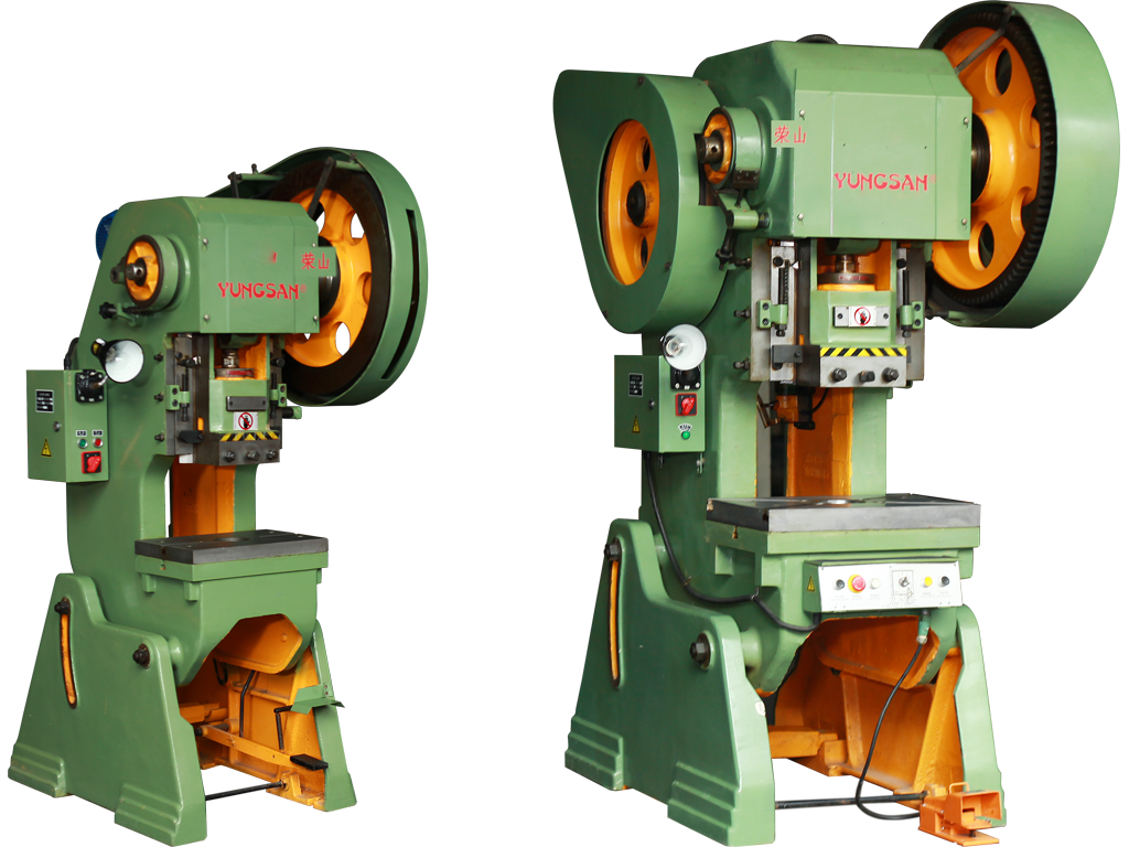
Main Components of a Power Press
The design of a Power Press involves several key components that work together to perform heavy-duty operations efficiently. Each component plays a vital role in ensuring the machine operates smoothly and safely.
1. Frame
The frame of a Power Press provides structural support and houses all the other components. Typically made from cast iron or steel, the frame must withstand the significant forces generated during operation without deforming. It ensures stability, precision, and durability, which are crucial for maintaining accuracy during repeated pressing cycles.
2. Flywheel
The flywheel stores rotational energy generated by the motor and releases it steadily to drive the ram. By maintaining consistent energy output, it helps ensure uniform pressure during each pressing cycle. The flywheel’s size and speed are carefully calculated based on the machine’s capacity and the type of operation it will perform.
3. Crankshaft and Connecting Rod
The crankshaft and connecting rod convert the rotary motion of the flywheel into linear motion, which drives the ram downward. This mechanism allows the press to deliver controlled and powerful strokes necessary for shaping or cutting materials. The precision of these components directly affects the accuracy and efficiency of the machine.
4. Ram or Slide
The ram, sometimes referred to as the slide, is the part of the Power Press that physically applies pressure to the workpiece. It moves vertically under the guidance of the frame and is designed to withstand extreme forces without bending or deflecting. Various attachments, such as punches or dies, can be fitted to the ram to perform specific operations.
5. Die and Tooling
Dies are specialized tools attached to the ram and the bed of the press to shape, cut, or form materials. They come in various designs, depending on the intended operation. Proper alignment and secure fastening of dies are critical to ensuring accurate and safe production.
6. Bed
The bed, also known as the table, supports the material being processed. It works in tandem with the ram and die to create the desired shape or cut. A rigid and stable bed prevents material movement during operation, enhancing precision and minimizing the risk of defects.
7. Drive Mechanism
Power Press machines can be driven mechanically, hydraulically, or pneumatically. Mechanical presses rely on flywheels, gears, and crankshafts, while hydraulic presses use pressurized fluid to generate force. Pneumatic presses operate using compressed air. Each drive type offers unique advantages depending on the force, speed, and precision required.
8. Safety Devices
Modern Power Press machines include several safety features to protect operators. These may include guards, emergency stop buttons, light curtains, and two-hand control systems. Ensuring these safety mechanisms are in place and functional is critical for preventing accidents and injuries in the workplace.
Working Principle of a Power Press
The basic working principle of a Power Press involves converting energy from a motor into mechanical force to deform or cut a material. In a mechanical Power Press, the motor drives the flywheel, which transfers energy through a crankshaft and connecting rod to move the ram. The ram presses the material against the die with sufficient force to achieve the desired shape or cut. Hydraulic presses operate differently by using pressurized hydraulic fluid to move the ram directly, offering precise control over force and speed. Pneumatic presses utilize compressed air to achieve a similar motion for lighter applications.
The operation of a Power Press follows a consistent cycle: positioning the material, activating the press, applying pressure via the ram, and removing the finished part. This cycle can be repeated rapidly, which makes the machine suitable for mass production. The precision and reliability of this process depend on the quality of the components and the alignment of the die and ram.
Conclusion
Understanding the components and working principles of a Power Press is essential for optimizing its performance and ensuring safe operation. From the sturdy frame and flywheel to the precision ram and dies, each part plays a crucial role in achieving accurate and efficient results. By adhering to proper maintenance procedures and safety protocols, industries can maximize productivity and extend the lifespan of these versatile machines. Whether mechanical, hydraulic, or pneumatic, the Power Press remains a cornerstone of modern manufacturing.